How to Draw Er Diagram for Hospital Management System
Database is absolutely an integral part of software systems. To fully utilize ER Diagram in database technology guarantees you to produce high-quality database design to employ in database creation, direction, and maintenance. An ER model also provides a means for communication.

Today we're going to walk you through everything you demand to know about ER Diagramming. Past reading this ERD guide, you will get the essential knowledge and skills nearly ER Diagrams and database design. You volition learn things similar what is ERD, why ERD, ERD notations, how to describe ERD, etc. along with a bunch of ERD examples.
Design Database Faster, Better and Easier
Are you looking for a Gratuitous ERD tool for creating data models faster, easier and quicker? Visual Paradigm Community Edition provides you lot with an ERD editor for database design. It is an international award-winning modeler, and still it is easy-to-use, intuitive & completely free.
Costless Download
What is an ER diagram (ERD)?
First of all, what is an Entity Relationship Diagram?
Entity Relationship Diagram, also known as ERD, ER Diagram or ER model, is a type of structural diagram for employ in database blueprint. An ERD contains different symbols and connectors that visualize ii of import information: The major entities within the system scope, and the inter-relationships among these entities.
And that's why information technology'southward called "Entity" "Human relationship" diagram (ERD)!
When we talk about entities in ERD, very oftentimes nosotros are referring to business objects such as people/roles (e.g. Student), tangible business organisation objects (e.chiliad. Product), intangible business objects (east.thousand. Log), etc. "Relationship" is near how these entities relate to each other within the system.
In a typical ER design, y'all can discover symbols such equally rounded rectangles and connectors (with dissimilar styles of their ends) that depict the entities, their attributes, and inter-relationships.
When to describe ER Diagrams?
And so, when do we describe ERDs? While ER models are mostly developed for designing relational databases in terms of concept visualization and in terms of physical database blueprint, there are still other situations when ER diagrams can assist. Hither are some typical use cases.
- Database blueprint - Depending on the scale of change, it can exist risky to alter a database structure directly in a DBMS. To avoid ruining the data in a product database, information technology is of import to plan out the changes carefully. ERD is a tool that helps. Past drawing ER diagrams to visualize database blueprint ideas, yous take a hazard to identify the mistakes and design flaws, and to make corrections before executing the changes in the database.
- Database debugging - To debug database issues tin can be challenging, peculiarly when the database contains many tables, which crave writing circuitous SQL in getting the information y'all need. By visualizing a database schema with an ERD, you lot have a full picture of the entire database schema. You can hands locate entities, view their attributes and place the relationships they accept with others. All these permit you lot to analyze an existing database and to reveal database problems easier.
- Database cosmos and patching - Visual Epitome, an ERD tool, supports a database generation tool that can automate the database creation and patching process by means of ER diagrams. So, with this ER Diagram tool, your ER design is no longer but a static diagram simply a mirror that reflects truly the physical database construction.
- Aid in requirements gathering - Determine the requirements of an information organization by drawing a conceptual ERD that depicts the high-level business objects of the system. Such an initial model can too be evolved into a concrete database model that aids the cosmos of a relational database, or aids in the cosmos of process maps and data catamenia modes.
ERD notations guide
An ER Diagram contains entities, attributes, and relationships. In this section, we volition get through the ERD symbols in item.
Entity
An ERD entity is a definable affair or concept within a system, such equally a person/role (e.yard. Student), object (eastward.g. Invoice), concept (e.g. Profile) or consequence (e.g. Transaction) (note: In ERD, the term "entity" is often used instead of "table", only they are the same). When determining entities, think of them equally nouns. In ER models, an entity is shown as a rounded rectangle, with its proper noun on top and its attributes listed in the body of the entity shape. The ERD example below shows an case of an ER entity.

Entity Attributes
Also known every bit a cavalcade, an attribute is a property or feature of the entity that holds it.
An attribute has a proper noun that describes the holding and a type that describes the kind of attribute it is, such as varchar for a string, and int for integer. When an ERD is drawn for physical database development, it is of import to ensure the use of types that are supported by the target RDBMS.
The ER diagram instance below shows an entity with some attributes in it.

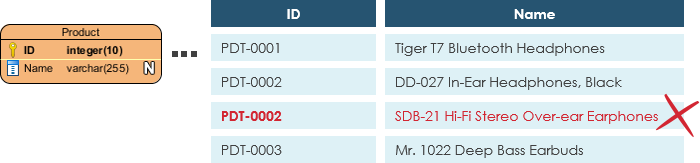
Chief Key
As well known equally PK, a main primal is a special kind of entity attribute that uniquely defines a record in a database table. In other words, there must not be two (or more) records that share the same value for the main fundamental attribute. The ERD instance below shows an entity 'Product' with a primary key attribute 'ID', and a preview of table records in the database. The third record is invalid because the value of ID 'PDT-0002' is already used by some other record.
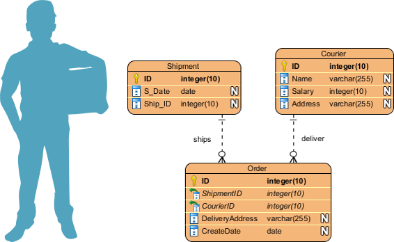
Foreign Key
Also known as FK, a foreign cardinal is a reference to a principal key in a tabular array. Information technology is used to identify the relationships between entities. Note that foreign keys need non be unique. Multiple records tin can share the same values. The ER Diagram case below shows an entity with some columns, among which a foreign cardinal is used in referencing some other entity.

Relationship
A human relationship between ii entities signifies that the 2 entities are associated with each other somehow. For example, a pupil might enroll in a course. The entity Student is therefore related to Form, and a relationship is presented equally a connector connecting between them.
Cardinality
Cardinality defines the possible number of occurrences in i entity which is associated with the number of occurrences in another. For example, 1 team has MANY players. When present in an ERD, the entity Squad and Player are inter-continued with a one-to-many human relationship.
In an ER diagram, cardinality is represented as a crow'due south human foot at the connector's ends. The three common cardinal relationships are 1-to-one, one-to-many, and many-to-many.
One-to-1 cardinality example
A one-to-one relationship is more often than not used to split up an entity in ii to provide information concisely and make it more understandable. The effigy below shows an example of a ane-to-i relationship.

One-to-Many cardinality example
A one-to-many relationship refers to the human relationship between two entities X and Y in which an instance of 10 may be linked to many instances of Y, just an instance of Y is linked to just one instance of X. The figure below shows an instance of a one-to-many relationship.

Many-to-Many cardinality example
A many-to-many relationship refers to the relationship between two entities X and Y in which X may be linked to many instances of Y and vice versa. The figure beneath shows an example of a many-to-many relationship. Annotation that a many-to-many relationship is split into a pair of one-to-many relationships in a physical ERD. You volition know what a physical ERD is in the next department.

Conceptual, Logical and Physical information models
An ER model is typically drawn at up to iii levels of brainchild:
- Conceptual ERD / Conceptual information model
- Logical ERD / Logical data model
- Physical ERD / Physical data model
While all the iii levels of an ER model incorporate entities with attributes and relationships, they differ in the purposes they are created for and the audiences they are meant to target.
A general agreement to the three information models is that concern annotator uses a conceptual and logical model to model the business organisation objects exist in the system, while database designer or database engineer elaborates the conceptual and logical ER model to produce the concrete model that presents the physical database structure ready for database cosmos. The table below shows the difference between the three data models.
Conceptual model vs Logical model vs Data model:
| ERD features | Conceptual | Logical | Physical |
|---|---|---|---|
| Entity (Proper noun) | Aye | Yeah | Yep |
| Relationship | Aye | Yes | Yes |
| Columns | Yes | Yes | |
| Column's Types | Optional | Yes | |
| Primary Primal | Yep | ||
| Strange Key | Yes |
Conceptual data model
Conceptual ERD models the business objects that should exist in a organization and the relationships between them. A conceptual model is developed to present an overall flick of the organization past recognizing the business objects involved. It defines what entities exist, NOT which tables. For example, 'many to many' tables may be in a logical or physical data model but they are just shown as a human relationship with no cardinality under the conceptual data model.
Conceptual data model example

Note: Conceptual ERD supports the utilise of generalization in modeling the 'a kind of' relationship between ii entities, for case, Triangle, is a kind of Shape. The usage is similar generalization in UML. Notice that only conceptual ERD supports generalization.
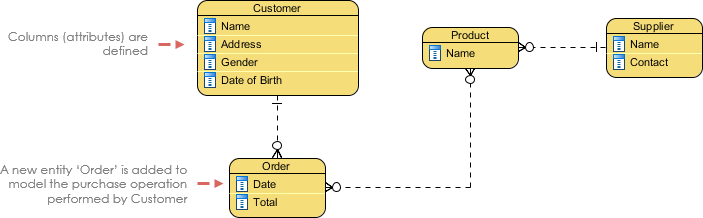
Logical information model
Logical ERD is a detailed version of a Conceptual ERD. A logical ER model is developed to enrich a conceptual model by defining explicitly the columns in each entity and introducing operational and transactional entities. Although a logical data model is nevertheless independent of the actual database system in which the database will exist created, you can still accept that into consideration if it affects the design.
Logical information model example
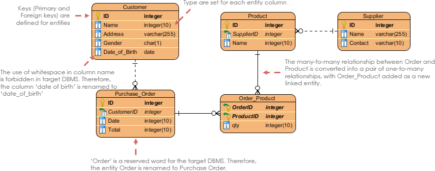
Concrete data model
Physical ERD represents the actual blueprint blueprint of a relational database. A physical information model elaborates on the logical data model by assigning each cavalcade with blazon, length, nullable, etc. Since a concrete ERD represents how data should be structured and related in a specific DBMS it is of import to consider the convention and restriction of the actual database system in which the database will exist created. Make sure the column types are supported by the DBMS and reserved words are not used in naming entities and columns.
Physical data model instance
How to draw an ER diagram?
If you find information technology hard to go started with drawing an ER diagram, don't worry. In this section, nosotros volition give you some ERD tips. Effort to follow the steps beneath to understand how to depict an ER diagram effectively.
- Make sure yous are clear well-nigh the purpose of drawing the ERD. Are yous trying to nowadays an overall arrangement architecture that involves the definition of business objects? Or are you lot developing an ER model ready for database creation? You must exist clear about the purpose to develop an ER diagram at the right level of detail (Read the section Conceptual, Logical and Physical Information Models for more details)
- Make certain you are articulate about the telescopic to model. Knowing the modeling telescopic prevents you from including redundant entities and relationships in your blueprint.
- Depict the major entities involved in the scope.
- Ascertain the properties of entities by adding columns.
- Review the ERD advisedly and check if the entities and columns are enough to store the information of the system. If not, consider adding boosted entities and columns. Commonly, you tin identify some transactional, operational and consequence entities in this step.
- Consider the relationships betwixt all entities and relate them with proper cardinality (due east.chiliad A one-to-many between entity Client and Gild). Don't worry if there are orphan entities. Although it'south non common, it's legit.
- Utilise the technique of database normalization to re-structure the entities in a way that can reduce data redundancy and improve data integrity. For example, the details of the manufacturer might be stored under the Production entity initially. During the process of normalization, you may observe that the detail keeps repeating records over records, and so you tin can carve up it as a divide entity Manufacturer, and with a strange primal that links between Product and Manufacturer.
Data model examples
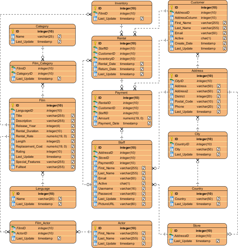
ERD example - Flick Rental Organization
ERD example - Loan System

ERD example - Online Store

Using ERD with Data Menstruation Diagram (DFD)
In organization analysis and design, Information Menstruation Diagram (DFD) can be fatigued to visualize the menstruum of information within system processes. In a Data Flow Diagram, there is a symbol called Data Store, which represents a database table that provides the data needed past the system.

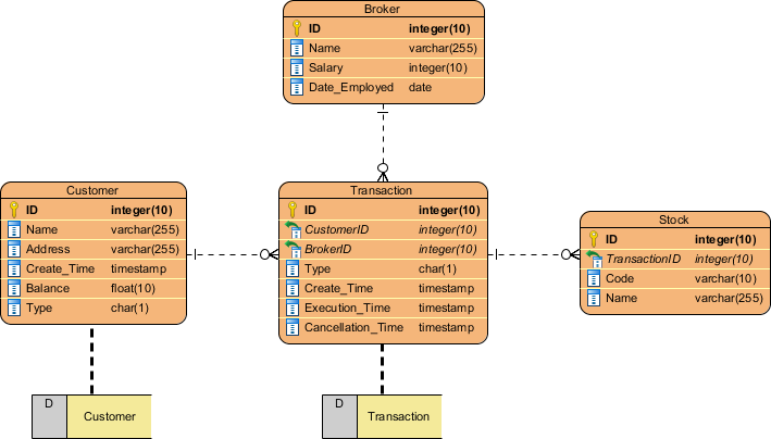
Since a physical ER Diagram provides a blueprint of an bodily database, the entities in such an ERD are aligned with datastores in a DFD. You tin can draw ERD as a complement to DFD past representing the construction of data that flows within a system, or, on the contrary, to draw DFD in complementing an ERD by showing how the data will be utilized by the system in runtime.
Using ERD with BPMN Business Process Diagram (BPD)
In business process mapping, BPMN Business Procedure Diagram (BPD) can be fatigued to visualize business workflows. In a Business Process Diagram, there is a symbol called Data Object, which represents the data input into / output from process activities.

Since a conceptual and logical data model provides a high-level view of business objects within a arrangement, the entities in such ERDs are aligned with data objects in BPD. Y'all can draw ERD every bit a complement to BPD past representing the structure of data objects needed by a business workflow, or, on the contrary, to describe BPD in complementing an ERD by showing how the data will be utilized throughout a business procedure.

Choosing an ERD tool
It takes time and effort to develop a information model with ERD. A helpful database design tool should be able to reduce your time and endeavor spent. Visual Paradigm provides you lot with not only an ERD tool but also a set up of visual modeling features that helps yous depict faster and easier. It supports well-nigh of the popular relational database management systems in the market today both in terms of database design, database generation, and ERD reversal.

The ERD designer is bachelor in Visual Image Modeler, which costs only U.s.a. $6 per calendar month. We would recommend you download and accept a effort. 30 days of Complimentary evaluation is offered. No credit card required.
Design your database now
You've learned what an ER diagram is and how to create ERD for database design or data modeling. It's fourth dimension to endeavor it yourself. Get Visual Paradigm Community Edition, a costless ERD tool, and develop your own ER model with the free ER Diagram tool. It's piece of cake-to-use and intuitive.
Gratis Download
Source: https://www.visual-paradigm.com/guide/data-modeling/what-is-entity-relationship-diagram/
0 Response to "How to Draw Er Diagram for Hospital Management System"
Postar um comentário